So begins the big job that we've been putting off for the longest time. The front dashboard and electrics. The lower dash in the defender had numerous scratches, screw holes and cutouts from previous owners. There were also unidentified holes and wires behind the rear wash wiper control panel.

Fortunately the whole process was made easier due to the quality and depth of diagrams on various websites as well as the detailed notes in the Defender 300Tdi workshop manual. Below is an example of the instrument panel. All parts are labelled which helped when checking that the fittings were as per factory and when sourcing replacement parts.

First to be removed was the instrument panel. This was a pretty fiddly affair. Bundles of photos taken during the process to help ensure that the process could be successfully reversed. Some examples below.

Behind the LED panel

Behind the LED panel RHS

Behind the LED panel LHS

Behind the hazard warning switch panel

Behind the ignition switch
Checking the fuses
Some of the fuses were clearly not the default factory values.

Examination of the fuses comparing the book to actual fitting as follows:
Fuse Number
|
Book (Amps)
|
Actual (Amps)
|
Electrical circuit
|
1
|
15
|
15
|
Hazard
|
2
|
20
|
20
|
Interior lamp, horn
|
3
|
15
|
15
|
Wipers Washer rear
|
4
|
10 (15)*
|
7.5
|
Wipers Washer front
|
5
|
15
|
15
|
Heater
|
6
|
7.5
|
7.5
|
Rear fog
|
7
|
5
|
5
|
Radio
|
8
|
15
|
15
|
Heated rear
|
9
|
10
|
10
|
Cigar lighter
|
10
|
20
|
20
|
Alarm sounder
|
11
|
7.5
|
7.5
|
Headlamp RH dipped
|
12
|
7.5
|
7.5
|
Headlamp LH dipped
|
13
|
7.5
|
7.5
|
Headlamp RH main
|
14
|
7.5
|
7.5
|
Headlamp LH main
|
15
|
5
|
5
|
Side lamps LH
|
16
|
5
|
5
|
Side lamps RH
|
17
|
15
|
15
|
Stop & reverse lamp
|
18
|
20
|
20
|
Air con
|
19
|
5
|
7.5
|
Air con
|
20
|
5
|
30
|
Alarm
|
So we had too low a rated fuse in slot 4 and two overrated fuses in slots 19 and 20.
Fuse number 4 is stated as being 10 amp in the workshop manual. However, the fuse box cover and electric manual both suggest 15 amp. Decided to fit 15 amp fuse.

Trailing wire not connected.

Trailing wire loose.
Fuse 19
Fuse 19 is made up of two connectors (37/38) and should be coloured brown and brown/slate grey respectively.
The unknown wire from the immobilisation spider "terminated" behind connector 38 of fuse 19 in that it has been inline soldered, taped and then the original brown/slate grey cut. This unidentified wire could therefore clearly be removed.
Fuse number 4 is stated as being 10 amp in the workshop manual. However, the fuse box cover and electric manual both suggest 15 amp. Decided to fit 15 amp fuse.
Also, ever since we picked up Sluggie, I've had some reservations about the wiring of the immobilisation spider under the seat box. There was an unidentified wire coming from there to the inside of the fuse box lid - highlighted in red below.

Trailing wire not connected.

Trailing wire loose.
Fuse 19 is made up of two connectors (37/38) and should be coloured brown and brown/slate grey respectively.
The unknown wire from the immobilisation spider "terminated" behind connector 38 of fuse 19 in that it has been inline soldered, taped and then the original brown/slate grey cut. This unidentified wire could therefore clearly be removed.

Also, further examination of fuse 19 revealed that connector 39 was missing.

Turns out that the missing brown connector 39 was loose in the wiring loom - brilliant. Nothing like a positive from the battery hanging loose in the wiring loom. So the following fixes have been applied to essentially put the fuse box back to factory standard:
- Unidentified wire removed completely.
- New spade connector (STC4034) added to the brown/slate grey cable located back in slot 38.
- The brown spade connector located in slot 37.
- Original land rover fuses sourced and correctly fitted.
Obviously had to ensure all the fuses lined up the same way too.

Immobilisation Spider
Looks like at some point the immobilisation spider had been disabled using part AMR4956. Various searches on the internet have questioned the reliability of immobilisation spiders. Wondering if this is why the part had been fitted. In any case, more than happy with this modification. Just not so enthusiastic about how it was left in the battery box.

Spaghetti wiring around the immobilisation.
The immobilisation spider casing was therefore removed:

Immobilisation spider case removed.
The rivets drilled out and the spider module removed:
And AMR4956 connector fitted inside with a new grommet. The wiring in the battery box now looking much more tidy.

Cigarette light/Rear wash wiper panel
Immobilisation spider case removed.
The rivets drilled out and the spider module removed:
And AMR4956 connector fitted inside with a new grommet. The wiring in the battery box now looking much more tidy.


Dashboard with various cutouts, screw holes, etc...
The original cigarette lighter/rear wash wiper panel had an extraneous hold drilled into the middle - see image above. There was also an unidentified cable/plug located behind the hole. Upon dashboard removal, it became clear that the other end of the cable had simply been cut and was hanging loose in the behind the dashboard. This cable and plug have therefore been removed.
A new panel has been fitted (see below) as well as a new replacement cigarette lighter (the old one was loose and rattling in the fitting) and new rear wash wipe switch. New bolts/washers/nuts have also been added to secure the panel to the dashboard - these were previously missing.
Fuse Cover
The original fuse box had some extraneous holes drilled in the bottom left. The spare fuse holder, fuses and fuse removal tool were also missing.

Old fuse box cover with holes

Old fuse cover with sticker show fuse sizes.
Managed to source an excellent condition cover off ebay. It was not possible to source a new one that had the same fuse layout sticker AMR5861 or obtain the sticker individually.

Outside of replacement fuse box cover
There were no fuses with the purchase but managed to also source some original genuine Land Rover fuses to populate the spare fuse bank. All now back to factory standard.

Inside replacement fuse box cover
10AS

10AS unit hidden behind the ignition switch

10AS unit


The 10AS alarm unit has various controls and settings, e.g. courtesy light control and determines whether hazards flash when alarm is remotely set/unset.

10AS unit hidden behind the ignition switch
These have never worked so decided to remove the 10AS unit and have it checked and reprogrammed by to factory settings. Used Paul Brown of Technozen Electronics for this since the process requires specialist test book tools.

10AS unit
When removing the 10AS unit noticed that the bolts used were not original. Only one bolt had a washer. Correct bolts sourced - 2xSH105201L.
The unit came back from Paul promptly and a report of the settings made available. Note the alarm codes have been hidden! His services is top notch.


Dashboard refitThe unit came back from Paul promptly and a report of the settings made available. Note the alarm codes have been hidden! His services is top notch.

Original Settings

Modified Settings
The entire upper and lower dashboard was removed. This allowed full inspection of the bulk head and further allowing the console modifications detailed below to be carried out.

Wires everywhere but now understanding them all.

Refitting the Instrument Panel


Managed to source another C914 flying lead and made up as per the schematic.


Once fired up, the rev counter worked a treat.
<PHOTO>
However, when running with the lights on, it was clear that the rev counter bulb is way too bright. As such, have replaced the bulb with the original clock one.
Next, the cigarette lighter, rectangular clock and rear wash wipe switch were housed on the metal plate. All ready to mount back onto the dash. This would now allow it to be fitted to the instrument panel and connected to the existing clock connector that was previously used for the old clock.


Door Hinge Covers


The panel was cleaned up. All the parts look original given there manufacturing time stamping/labelling.

Rear of instrument panel

Front of instrument panel
Really liked the idea of fitting a rev counter. Reading various forums suggested that some folk had done so by fitting part YAE100800. It's a genuine Land Rover part and can be fitted into the instrument panel.

Essentially the clock was removed from the instrument panel and replaced with the rev counter, albeit fitting it next to speedometer and shifting over the fuel gauge. Did not want to loose a clock so sourced a rectangular old style one (PRC4370) which could be fitted on the centre dash between rear wash wipe and cigarette lighter. Lucky manged to find one in great condition on a metal original centre dash plate.

The original clock on the main instrument panel had a handy connector, C914, which had flying leads. This therefore made it possible to connect new electrics while keeping the wiring loom as per factory.

Managed to source another C914 flying lead and made up as per the schematic.
- Positive terminal connected to ignition controlled feed (White)
- Negative terminal connected to the negative terminal of the illumination bulb (Black)
- Terminal 2 connected to the "W" terminal on the alternator (Grey)
- Positive terminal of the illumination bulb connected to C914 (White/Red)
- Negative terminal of the illumination bulb connected to C914 (Black)
- Permanent feed from C914 connected to the new clock on the center dash (Purple)
The set of 3 dip switches on the back for the rev counter have been set as 1,3 up and 2 down. This giving an idle rev reading of around 750 to 800 rpm.

Below is the rear of the dash with the new rev counter fitted.


Front below.

Then a cable to the alternator was then made up. The W connector can be seen in the image below.

A cable with a ring crimp connector for the terminal was fitted.

Given the routing of the cable would pass by the exhaust from the engine, decided to sleeve the cable in a heat resistant material and shrink wrapped at the end to help keep it sound.

Attached to the alternator as shown below.

Routed behind the screen wash tank and across the back of the bulkhead. Fitted it through an existing grommet. Also took the opportunity to route through the new radio aerial cable all the way through to the dash. Earlier on when it was fitted a connection was made to the existing cable feed. Now there are no joins between the aerial and the radio.

Once fired up, the rev counter worked a treat.
<PHOTO>
However, when running with the lights on, it was clear that the rev counter bulb is way too bright. As such, have replaced the bulb with the original clock one.
Next, the cigarette lighter, rectangular clock and rear wash wipe switch were housed on the metal plate. All ready to mount back onto the dash. This would now allow it to be fitted to the instrument panel and connected to the existing clock connector that was previously used for the old clock.

Rear of the center dash panel. Illumination connectors piggy backed to the cigarette lighter fitting.

Front of center dash panel looking like new.
It took some doing but eventually managed to source a lower dash panel that was in really good condition. No holes, marks, rips, etc...

Image of dash as taken by seller.
Once it arrived, opened it up, clean it out thoroughly, replaced all the screws, lubed up the vent flaps, cable, etc... and fitted new vent rubbers.

Replacement lower dash all cleaned up.
Before fitting it back though, some clean up of the bulk head was required. In particular, the area around the heater outlet and grommet needed attention.

Old grommet stuck to surround.

After clean up.

New grommet sourced.

Double sided sticky sheet cut to fit the grommet.

New grommet fitted.
In the refit, managed to identify that the following screws/bolts/washers/gaskets/etc... all needed to be either replaced back to factory standard or were simply missing.
Steering Column Nacelle
Stiffener
1xWF105001L - Washer,M5,starlock
Dash Vents
4xAB606064L - Screw-self tapping AB,No 6 x 3/4
4xSE105401 - Bolt, M5 x 40
2xAB608031L - Screw, No 8 x 3/8
1xSE105161L - Screw-pan,M5 x 16
1xSE105161L - Screw-pan,M5 x 16
Instrument panel - 4 screws
2xAD606044L - Bolt,No 6 x 1/2
2xWK606214L - Washer-cup,No 6
2xMWC9322 - Nut-spring-u type,No 6
2xAB606044L - Bolt,Self tapping,No 6 x 1/2
2xWF704064 - Washer-starlock,4MM,No 6
2xMWC9322 - Nut-spring-u type,No 6
2xAD606044L - Bolt,No 6 x 1/2
2xWK606214L - Washer-cup,No 6
2xMWC9322 - Nut-spring-u type,No 6
2xAB606044L - Bolt,Self tapping,No 6 x 1/2
2xWF704064 - Washer-starlock,4MM,No 6
2xMWC9322 - Nut-spring-u type,No 6
Stiffener
4xAB608051L - Bolt,black,Self tapping, No8 x 5/8
4xWF703084 - Washer-starlock,3MM,No 8
Temperature Control Panel
2xSE808244 - Screw
2xWA105004L - Washer-Plain
2xMRC9922 - Spacer
1xAFU1248 - Washer
4xWF703084 - Washer-starlock,3MM,No 8
Temperature Control Panel
2xSE808244 - Screw
2xWA105004L - Washer-Plain
2xMRC9922 - Spacer
1xAFU1248 - Washer
Grab Handle
1xSE105121L - Screw, M5 x 121xWF105001L - Washer,M5,starlock
1xAC606104 - Screw-self tapping,counter sunk,No 6 x 1 1/4
Crash Pad
3xWC106044L - Washer-Plain,M64xAB606064L - Screw-self tapping AB,No 6 x 3/4
4xWA105001L - Washer,M5, flat
Wiper Motor Cover
Heater Gasket
Cigarette & Rear Wash
2xSE105204 - fixing facia plate,Bolt, M5
2xAFU1248 - fixing facia plate,Washer
2xWC105001 - fixing facia plate,Washer-Plain,M5
2xNH105041L - Nut-hexagonal,M5
1xYUJ10037L - Lighter
10xAB608054L - Bolt,Self tapping,No8 x 5/8
10xAFU1248 - fixing facia plate,Washer
1xMTC6871
Door Hinge Covers
1xMUC3036 - Door check strap cover RH
1xMUC3037 - Door check strap cover LH
2xAB608064L - Screw self taping No8 x 3/4
1xMUC3037 - Door check strap cover LH
2xAB608064L - Screw self taping No8 x 3/4
Battery Box
Really glad to be tackling the cabling in the battery box. Wanted to get it ready with a feed and isolation switch ready for a winch at some point. Made up some new cables.

Crimp tool borrowed from a friend at work.

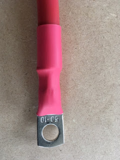
Stripping prior to fit of closed connector. The following strip lengths for the different gauge cable and diameter of bolt connector.
- 70mm2 x 10mm 23mm
- 50mm2 x 10mm 23mm
- 35mm2 x 10mm 19mm
- 25mm2 x 10mm 17mm
- 25mm2 x 5mm 19mm

Crimp connector attached.

Heat shrink wrap finished.

Negative lead made up.
No comments:
Post a Comment