The headlamp lighting circuit on a Defender unfortunately routes the current destined for the headlight lamps through the steering column switches. This results in at least two problems. Firstly, there is excessive electric wear on the column switches as a good amount of current gets dumped through switch. Secondly, there is a voltage drop at the headlight lamps due to a combination of the run lengths and the small gauge cable used to route the power.
As such, keen to have the dip and main beams switched via relays.
Pondered for some time on which way best to achieve this and came to the conclusion to route new cables from the headlight lamps back to the battery box and fit some relays there. The main reasons being to add all the new electrics in one place in the battery box.
As always, did not want to make any changes to our Defender that could not be reversed to return it back to factory standards if ever needed. The plan was as follows:
- Fit a dim dip bypass relay. There are bundles of other threads as to why this is necessary.
- Run separate looms from each of the headlamp lamps back to the batter box, i.e. two sets of dim, main beam and negative cables back to the battery box. Using dedicated negative cables reduces the current flow back through the chassis/bodywork and hopefully reducing any associated longer term catalytic corrosion.
- Fit a set of four relays in the battery box. Relay for each of the RH dim, LH dim, RH main and LH main circuits.
- Connect the headlamp power terminals of the relays to the auxiliary fuse box already fitted in the battery box. This ensuring each of the RH dim, LH dim, RH main and LH main headlight power circuits each having a separate fuse.
- Connect the engage side of the relays to the existing headlight fuses in the main fuse box in the center console. In this way, the switching side of the relays would also be fused.
Here's an image of the dim dip bypass relay. It replaces the dim dip relay situated behind the right hand side speaker on the main dashboard.

The looms for each of the headlights were made up with ceramic H4 bulb connectors as pictured below.

The following diagram being useful to ensure correct orientation of the pins being fitted. Image courtesy of some web page found by a search engine (apologies cannot recall to credit appropriately).

Each of the two looms was made up of 3 sets of 4mm squared cable, black (negative), brown (dip) and red (main). The RH loom being about 4.1m in length and the LH side being about 3m in length.

These were then encased in convoluted tubing for protection and routed from the headlights to the battery box. The image below shows the connection made by the new wiring loom to the headlight alongside the original loom and both being cable tied together.

Connection made to the LH side.
Was keen to route the new wire looms across the top of the wheel arches alongside the existing original headlight cables. This was a little trickier on the LH side as had to remove the wash bottle and heater duct assembly to gain access. However, felt it was worth it.

New LH side loom across wheel arch and behind heater.
When feeding the new loom from behind the heater and across the inside top of the LH side wheel arch, noticed that the tape protecting the original cables had taken some abuse. That said, not enough to damage the cables (yet). To ensure the indicator and side light cables are not going to be at further risk in the future, decided to cover this portion of the original loom with some taped split conduit.


Conduit protecting LH side loom.
The old heater gasket was also removed follwed by cleaning up the fan housing and cold air duct assembly. The rubber value assembly intake which is located in the cold air duct assembly in particular needed a good clean out. Loads of debris which falls through the wing top gets trapped in the rubber valve.

Cold air duct assembly with new gasket.
Once the cold air duct assembly was back in position, a bit of fiddling ensured that there is a good seal to minimise any exhaust gases from the engine bay making their way through the heater and into the cab.
Double checking the alignment of gaskets and free flow of air through to heater.

New cables run across back of the bulkhead.

New cable runs heading down onto chassis and into the inside side of the battery box.
The next task was to build the relay station. Sourced a relay housing that could take four relays and fitted it to the inside side of the battery box. The diagram below shows the relay box, the locations of the power take up from the auxiliary fuse box as well as the new loom entry locations.
The auxiliary fuse box also allowed the negative returns from the headlight looms to be connected to individual posts, with all of them being on a common earth plate connected directly to the battery.

The image also shows the auxiliary fuse box top right.
Really liked this relay station because of the following:
- A yellow plastic housings to provide physical strength to the connectors when fitting the relays.
- A plastic back plate that covered over all the connectors at the back prior to mounting.
- Enough access for cables to run from behind the relay housing out to where needed.
- A front cover for the relays (not fitted in image above).
The wiring connections for the relay station is as follows:

The four mixed colour coded wires that engage the relays were then connected to the main fuse box located under the center of dash. These being the fused side of the column switches, i.e. pins 22, 24, 26 and 28 respectively (blue/black, blue/pink, blue/orange and blue/slate). Fuse positions 11, 12, 13 and 14.

This was simply a matter of:
- Removing the four fuses.
- Pushing out the pins from locations 22, 24, 26 and 28. These being the cables that originally went to the headlamps.
- Crimping new fuse connectors to the new wires from the relay.
- Putting new fuse connectors into corresponding fuse holes.
- Replacing the fuses.

Original wires left in place behind the fuse box.
Left the original cables behind the fuse box and covered them with heat shrink wrap so as not to cause any electrical issues.
Then finished off the relay station by fitting the relays and front cover.

In this way, each of the wires to engage the relays are protected by the main fuse box (7.5amp fuses) and each of the relay switched power cables to the headlights are protected by the auxiliary fuse box (7.5amp fuses).
During the fitting, thought it would be a good idea to test and compare the old wiring loom performance with that of the new one. Below is an image cast on my garage door when switched to main beam. The glow on the RH side being that of the new loom and the glow on the LH side being that of the old loom.

Comparison of old loom (LH) and new loom (RH) with original lamps.
Hard to capture on the image, however, the difference was quite striking. With the now up rated wiring, then decided to fit some OSRAM Night Breaker lamps.
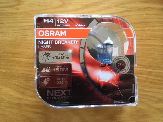
OSRAM Night Breakers
Again, did a compare on the garage door. The RH side being that of one of the Night Breaker lamps and the LH side being that of the old lamp. Both sides being on the new looms.

Comparison of old lamp (LH) and Night Breaker lamp (RH) on new looms.
Then looking head on at our Defender, you can clearly see the difference with the Night Breaker lamp. Looking at this image, the LH side being that of the Night Breaker and the RH side being that of the original lamp.

Now with both lamps upgraded to Night Breakers, we're really happy with the end result.

No comments:
Post a Comment